2.0 Assembly of bracings
How come there also is indicated material missing in the lower breaking point towards the D-leg? The possibility of focusing weak shock waves making the bracing explode in both ends was outruled by calculations performed by experts at Caltech, Los Angeles, in 1986. The implosion in the lower part caused by the explosion in the upper part will only make the bracing burst, be sucked in, at a point were the combined under presure inside the bracing and the waterpressure outside the bracing is larger than the carrying capacity of the steel bracing. In this case it happened at a distance of 7.5.meters from the D-leg, see fig 6.1.1. Thus the shape of both fractures at the D4 bracing lower breaking point should look the same unless one or both have been manipulated. Photo 6.1.1 showns the D4 lower breaking point on the middle part of the bracing picked up from the seabed approximately one month later.
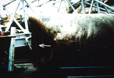
Photo 6.1.1; D4 lower breaking point.
Characteristic for this picture is the sucked in part on left side of the end fracture. Further the smoothly rounded edge shaped by water being sucked into the bracing in order to help equilize inside and outside pressure. Air is at the same time flowing back into the bracing through the upper breaking point. (This is further explained in section dealing with material testing of D4 upper breaking point.)
Section 2.1 Material testing of D4 upper breaking point
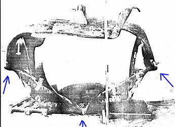
The D4 cut-off peace from the D-leg as presented in the Statoil and Commissions report has a different shape, see photo 6.1.2 and fig 6.1.2.
Photo 6.1.2 D4 lower breaking point at D-leg side after cut off.
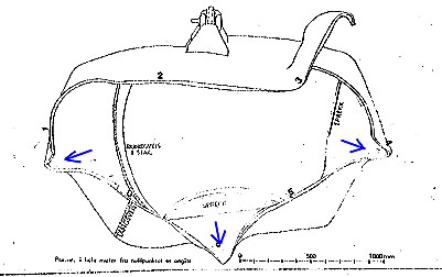
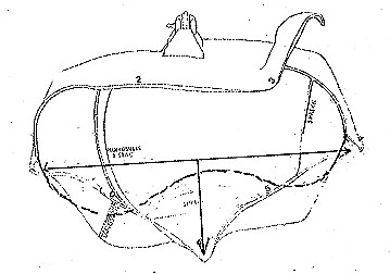
Fig. 6.1.2; D4 lower breaking point at the D-leg.